

Mounting the motor is one of the more difficult parts of the car and how we choose to install it depends very much on the sort of transmission we'll be using. In order to keep things as simple as possible, we would recommend using single speed, fixed gear, chain drive with 3/8" industrial chain, exactly the same as the Greenpower kit.
What do those terms mean?
Single speed: There will be one sprocket on the motor and another on the rear axle connected by a chain, there is no option for the driver to change gear as this must be done in the pits by physically replacing one of the sprockets for another with a different number of teeth.
Fixed gear: Both sprockets are rigidly fixed to their respective axles, so there is no option to freewheel.
3/8" industrial chain, or British Standard roller chain 06B-1 is widely available, inexpensive and very durable. Many teams use bicycle chain or smaller industrial chain such as 8mm and 1/4", these probably offer a small efficiency advantage but are more prone to jumping off sprockets due to misalignment, in several thousand miles of racing we've never had 3/8" chain come off its sprockets.
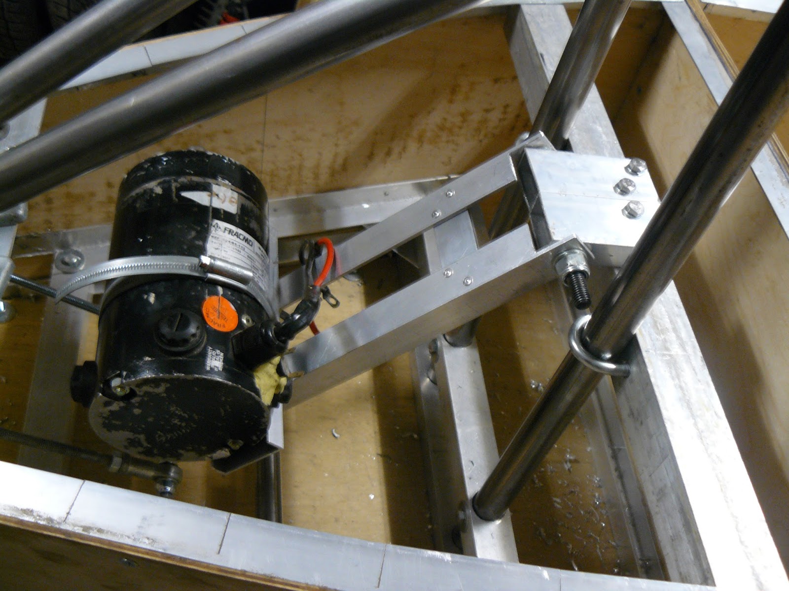
We're not using a separate chain tensioner so the mount needs to be adjustable so that the motor can be moved to get the correct tension. Having to change motor sprocket to adjust the gearing means we want good access to the motor so it's at the top of the compartment with mount and adjusters underneath and out of the way.
The motor mount is a simple, aluminium angle and channel bolted and riveted together, overall it's about 350mm long. At the left hand side is the top of the mount, the long bolt will pass through a pivot on the chassis allowing the whole mount to swing vertically. The two ball joints at the right hand side are part of the tensioning system.

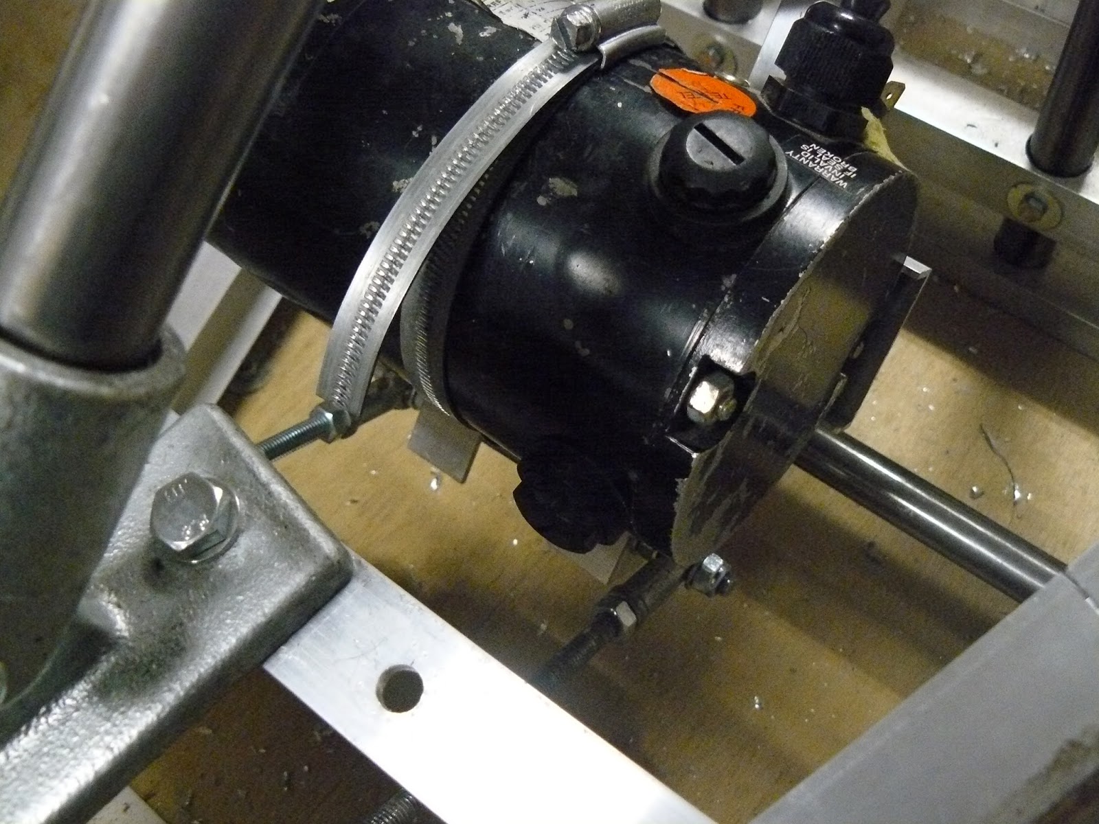
The standard Greenpower motor is supplied with a "foot" mount, they can be unreliable so in this case we have decided to remove it and strap the motor to a piece of channel with jubilee clips.

You can see how the motor locates securely into the channel. 50mm x 15mm works very well.
Two pieces of rectangular box section have been bolted to a crossmember and a hole drilled though both to take a 10mm bolt which is the pivot for the mount to swing on. The bolt is tightened up fairly well, it might be a pivot but only just has to be able to move, if it were too loose the motor could move slightly.

You can see a 14 tooth 3/8" sprocket on the motor shaft, and you'll have noticed this isn't a new motor, it's had a tough life!
M8 threaded rod is screwed into the ball joints and locked with nuts.

The other end of the threaded rod passes through the rear bulkhead. The aluminium channel has been used only to allow adjustment to be made from the outside of the car as access to the motor compartment will be difficult. The nuts are tightened against each other to lock the adjuster. It's not particularly elegant having the threaded rod at an angle but it works well enough and the angle introduces an element of triangulation which prevents the motor mount twisting under load.
It might seem strange to use two adjusters, they can be adjusted independently to ensure the motor is perfectly parallel to the rear axle and totally eliminated any twisting.
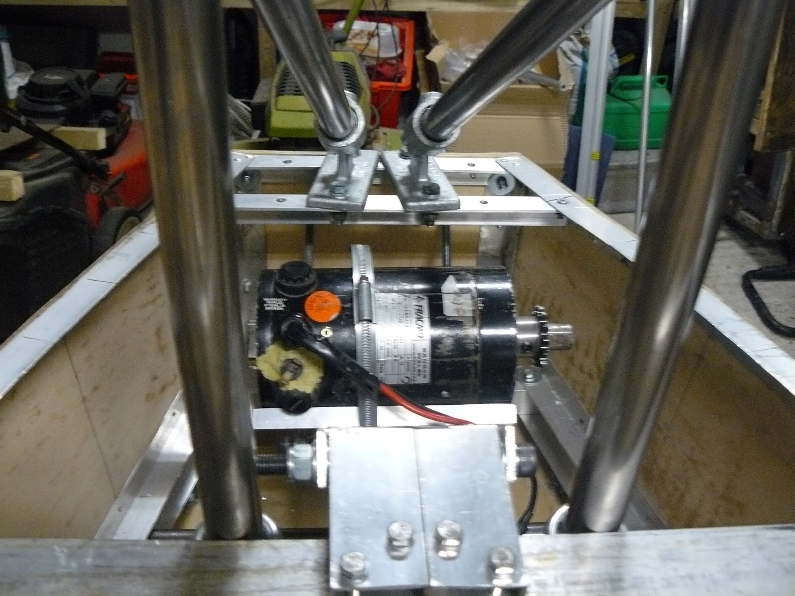
That's the motor in place, you can see it's easily accessible so changing sprockets will be straightforward and there's plenty of room for adding a cooling system if necessary. With the adjusters tightened up the motor is located very rigidly, this is important as we'll be switching it on and off with a relay which can put very high shock loadings on the mount; the reason why the standard "foot" mount can fail.
This is just one example of how to make a motor mount and probably not the best, but the whole thing weighs about 1kg, is totally rigid, and gives very fine adjustment of both chain tension and motor alignment, so it'll do the job well enough.
Tools used:
- Gary Coulden-Smith


