


Firstly here's a photo of one of the wheels, it's a 305 size with 32 spokes and disc brake hub with 20mm cartridge bearings, should be incredibly strong whilst also being easy to package on the car.
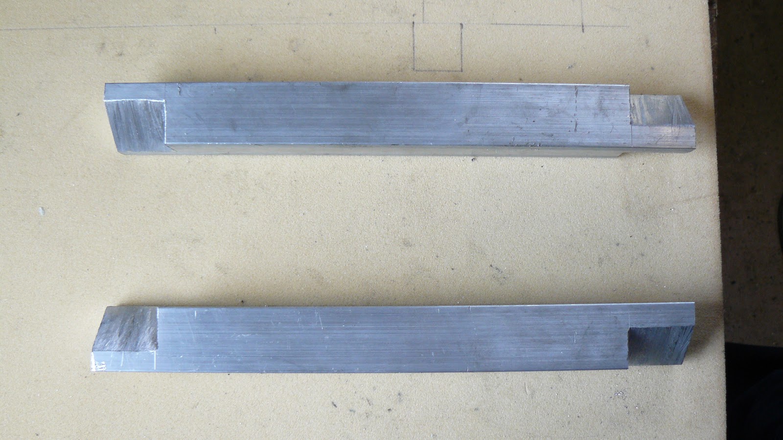
Each hub starts off as a piece of 30mm square section aluminium 280mm long, fillets 30mm long are cut from each end to leave a tongue about 15mm thick.
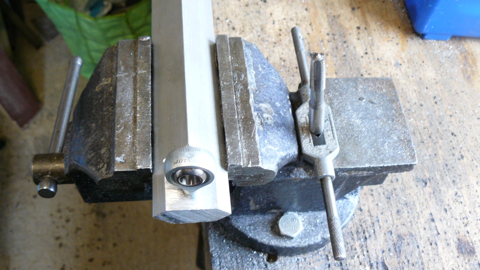
A hole is drilled and tapped M10 12mm from the end of the hub

A pair of hubs with 10mm rod ends installed. We've used half nuts on the stem of the rod end to ensure there's no movement.
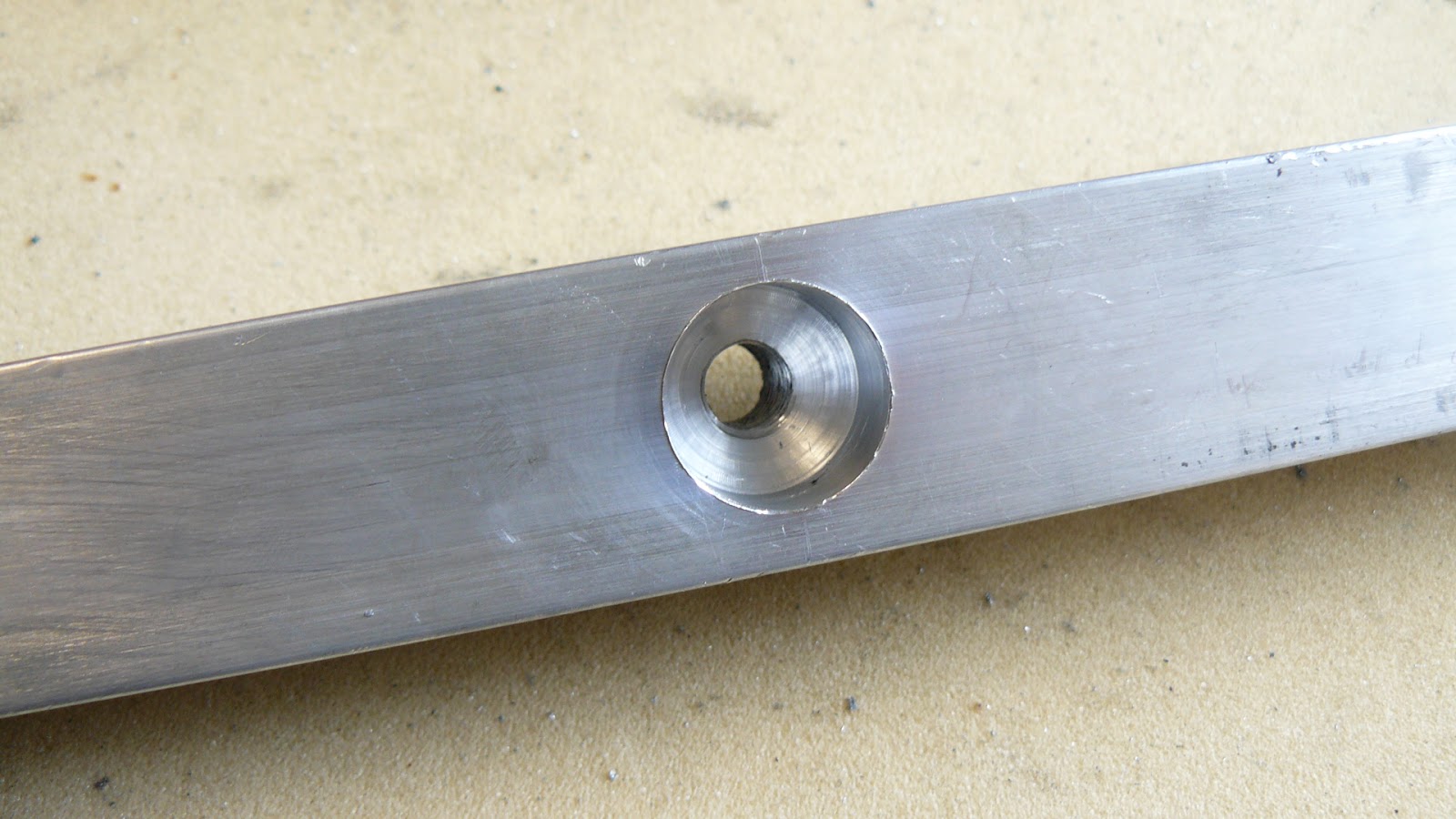
A 20mm hole for the stub axle is drilled 15mm deep and then an M10 tapped hole continues through the remainder of the hub. The actual location of this hole is dependent on factors such as wheel size and ground clearance so will vary from car to car.
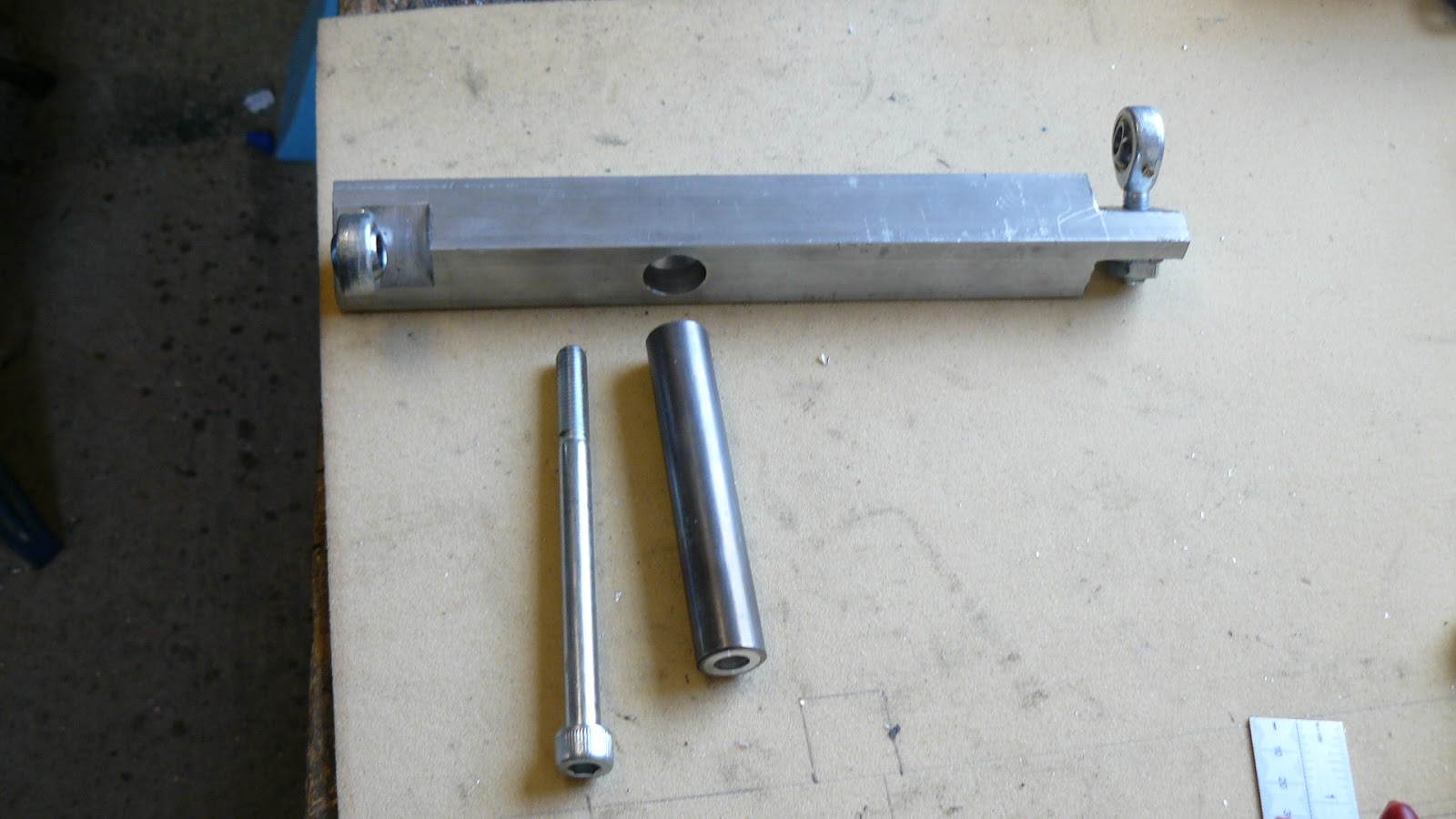
The stub axle is a length of 20mm x 2mm CDS tube, with 16mm x 3mm aluminium tube inside it. 10 minutes with emery cloth was enough to get a tight fit then a length of threaded rod used to press them together.

The 20mm hole is very slightly under size but the stub axle is pressed into it using a long M10 cap head bolt. It would be very difficult to remove the axle but that doesn't matter as I can't think of a reason why we would ever want to! The bolt is easily removed and will be used to retain the wheel and is also an integral part of the axle.

The hub is now temporarily installed, we didn't have quite the right length of bolts to hand and a selection of shim washers are required for fine adjustment of height so we'll sort that out once the wheels arrive. There is also a limited amount of camber adjustment available by screwing the rod ends in or out, we will be aiming for vertical.
The Greenpower kit car and lots of scratch built cars use rod ends in this way, notice how installing them at 45 degrees to the hub and 90 degrees to each other has created a considerable offset which is what creates the desired king pin angle. There is a potential problem with this design, as the hub turns it will start to tilt and the rod ends will eventually start to bind on the mounting bolt or spacing washers, fortunately we're only looking for 10 - 12 degrees of steering lock which is not enough to cause binding.
You can also see how the centreline of the axle is behind the axis around which the hub pivots, 23mm to be exact, this is known as "trail" and aids straight line stability as well as providing a self-centring effect, castor angles can be used for the same purpose but trail works just fine for us.
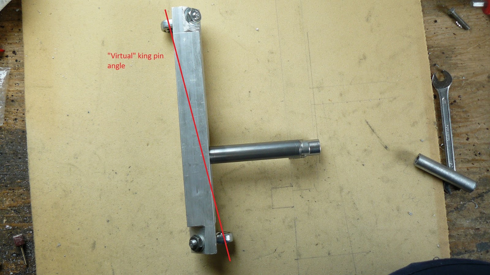
In effect the aluminium body of the hub is also the kingpin, the red line indicates what could be regarded as being a "virtual" kingpin and its effective angle of inclination. If we extend the line to the ground its point of contact should end up being about 10mm inboard of the tyre contact patch, not perfect centre point steering but that can lack "feel" and we've always avoided it for that reason whereas a small difference gives much better feedback and the driver is able to feel when the front wheels start to scrub.

Time to add the steering arms, each one is a piece of 10mm aluminium plate bolted to the top of the steering hubs; the set screws for which go into holes drilled and tapped M6.

Right hand steering arm is connected to the steering column with a length of M8 threaded bar and rod ends. The left hand side is still to be done and if there's time we'll clean up the many cutting marks and remove unnecessary material (drill a few holes!), if this were a team in a school there would be so many opportunities to practice workshop skills and end up with some really nice looking, hand made, components.

Now to be a bit controversial! There are plenty of steering calculation spreadsheets on the internet which let you work out the angle of the steering arms required to give ideal Ackermann steering angles; very simply Ackermann steering is when the front wheels are turned through different angles to match the radius of the turn they are making. The inner wheel has a larger steering angle than the outer wheel because it follows a smaller radius. In our experience teams agonise over this aspect of their car
Our combination of track and wheelbase means the angle between the steering arms and a line drawn across the car between the kingpins should be 82 degrees, however we want to keep the outer rod ends easily accessible and to do that the angle needs to be 96 degrees, reverse Ackermann, a disaster!!!!!
Or is it? Ignoring the hairpin at Ford Dunton the next tightest corner in a Greenpower race is at Alford where the 400 metre oval has two 15 metres radius 180 degree bends. With the outer wheel steering at the ideal angle to negotiate these corners the inside wheel should be turned at an angle of 5.43 degrees, but our imperfect steering will have only turned it 5.29 degrees, a difference of 0.14 degrees which isn't a lot (0.75mm at the wheel rim) and at every other circuit the corner radii are more like 40 metres and upwards giving an error of no more than 0.02 degrees. Quite simply we're talking about a difference that makes no difference, if you want to avoid embarrassing tyre squeal when driving your road car around a multi storey car park then you need something close to Ackermann steering, but it's not worth stressing about on a Greenpower car with wheels that will rarely deviate more than a couple of degrees from straight ahead.
There you have it, hubs that will provide safe and stable steering made using just a hacksaw, pillar drill, a couple of taps and spanners; all in about five hours.
- Gary Coulden-Smith


